


Quality Management
TORTAI Electronics adheres to the PDCA management improvement principle, based on ISO9001, ISO13485, ISO14001 quality system and IPC-A-600H standard, to optimise the internal management process and to enhance the supply chain management level, in order to ensure that our customers receive high quality products and manufacturing services. We strictly control the quality control points in the process, NPI product introduction, DFM inspection, PCBA manufacturing and testing, and conduct full training to form a perfect quality management system.

DFM Inspection
Check the following items of customer design PCB, BOM, schematic, and finished assembly manual:
Document version and last update time
Process: leaded/lead-free
Clear component part numbers and silkscreen
BOM with manufacturer’s brand and material number, description, and bit number
Confirmation of PCB fabrication process: material, board thickness, copper thickness, number of layers, surface treatment, character colour and special processes.
Reasonable PCB layer and board assembly method.
Provide correct SMT mounting files
Perfect program burning and function test programme.
Clear assembly manuals and schematics for finished products
Other special process requirements


New Product Introduction Meeting (NPI)
Organise sales department, engineering department, production department, purchasing department, quality department and other personnel to hold a new product introduction meeting.
Detailed introduction of the customer’s project background, product application scope, delivery and special requirements
Determine the internal customer number and product number
Define the production batch, procurement and delivery quantity
Evaluate the difficulty of the process and key quality control points of the project.
Define the procurement cycle of PCB and electronic components.
Propose draft production plan
Prepare fixtures, jigs, and auxiliary materials for the production process.
Define the test plan for customer’s products

PCB Production
We outsource PCB production and strictly control the following key quality points
High quality brand boards
Selection of top ten PCB suppliers
Continuously establish supplier relationship management
Have the ability to complete the process of 3 mil line width and pitch, multilayer, HDI, impedance, blind buried holes
All PCBs delivered to us must be 100% electrically tested.

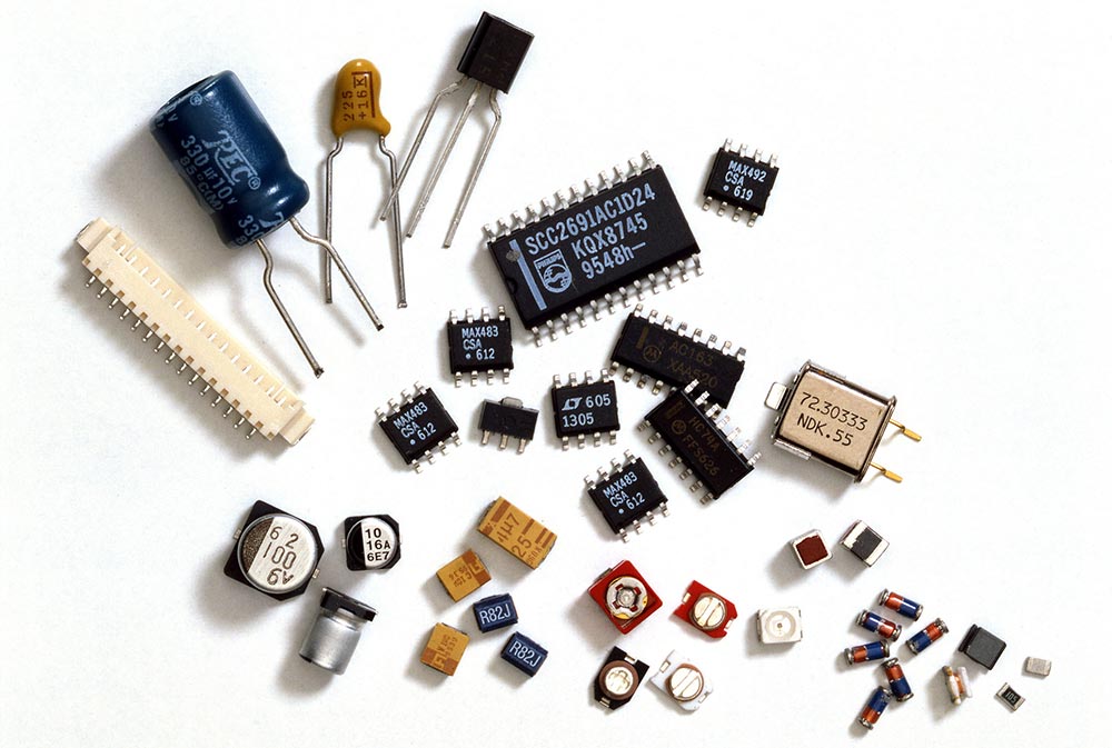
Purchase of Electronic Components
Procurement of 100% of the brands and material numbers specified in the customer’s BOM (unless the customer agrees in writing to procure other alternative materials due to procurement lead time).
Procurement of materials through regular channels such as primary agents and top traders.
Can provide the first-class agent certificate of origin
Good centralised purchasing advantages, shorter purchasing cycle, latest material year, stocking advantages, etc.
Provide perfect technical support from the original factory
IQC Incoming Material Inspection
Measure the thickness of PCB
Check the PCB through-hole and whether the ink is blocked, etc.
Check whether there is warping and deformation of PCB, and whether the silkscreen is clear.
Check the PCB for broken wires, skipped wires and other defects.
Place the PCB in the reflow soldering oven temperature test, check whether the yellowing or deformation
Check whether the batch number, material number and silkscreen of the incoming electronic components are consistent with the BOM.
The incoming electronic components are placed on the PCB bare board for pad or through-hole fit test.
Random inspection of incoming electronic components resistance, capacitance, etc., and compared with the BOM
Check the surface of the incoming electronic components whether there are scratches, deformation, broken legs, short legs and other appearance defects

Component Storage And Solder Paste Printing
Storage of sensitive components in professional constant temperature and humidity chambers
Bake some PCB/IC/BGA with strict requirements for 2-12 hours to remove surface moisture and enhance solderability.
Adopting first-class brand solder paste
Develop high quality laser stencil
Perfect solder paste freezing, thawing and stirring operation procedure.
Equipped with fully automatic solder paste printing machine to ensure the consistency and reliability of solder paste printing during mass production.

SMT Mounter
Adopting YAMAHA series high-speed automatic SMT mounter with accuracy up to 01005.
Component size range: 01005 0.3*0.15 mm²~200*125 mm².
Maximum height of processable components: 25.4mm.
BGA/CSP minimum ball pitch, ball diameter: 0.30mm, 0.15mm
Patch accuracy: ±22μm (3σ), ±0.05° (3σ)
Processable board size range: conventional 50*50 mm², sampling limit: 850*560 mm².
Plate thickness range: 0.3mm–6mm
Equipped with 10 temperature zone nitrogen + vacuum reflow soldering furnace, set up qualified furnace temperature curve.
Use the oven temperature tester to check the oven temperature every 4 hours and record it.
Use AOI optical detector for batch detection of wrong parts, missing parts, reverse, false soldering and other defects.
Use X-Ray to build up boards containing dense ball BGAs.
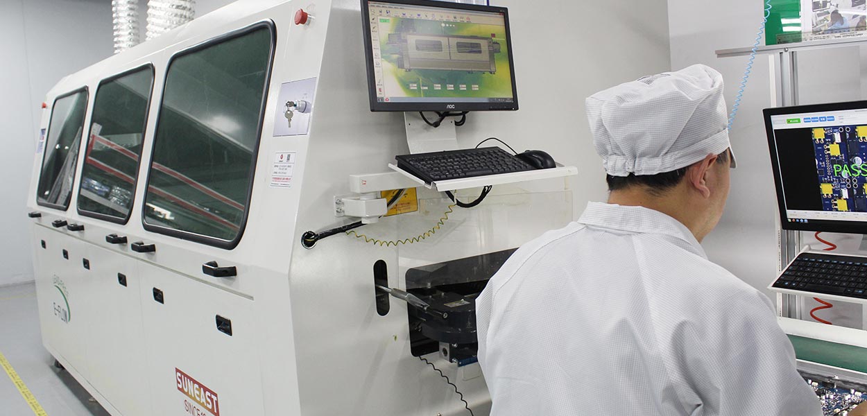
DIP Plug-In Processing
Strict workstation operating instructions
Wave soldering fixtures are prescribed for mass production to ensure the reliability and consistency of soldering.
Equipped with 2 plug-in production lines to meet the needs of mass production
Equipped with engraving machine, the engineering department according to customer requirements to open the test rack, the ability to complete the mainstream chip programme burning and functional testing
Solder Paste Inspection (SPI)
Solder Paste Quality Inspection: It is able to detect the quality of solder paste during the soldering process, such as thickness, shape, distribution, etc., in order to ensure the reliability and stability of the soldered connection.
Offset detection: able to detect the offset of solder paste position during the soldering process to ensure the accuracy and precision of soldering.
Defect detection: able to detect solder paste defects during the soldering process, such as too much, too little, misalignment and other issues, in order to avoid the impact on product quality and performance.
Data analysis and recording: able to record and store the results and statistics of each inspection for subsequent analysis and traceability.

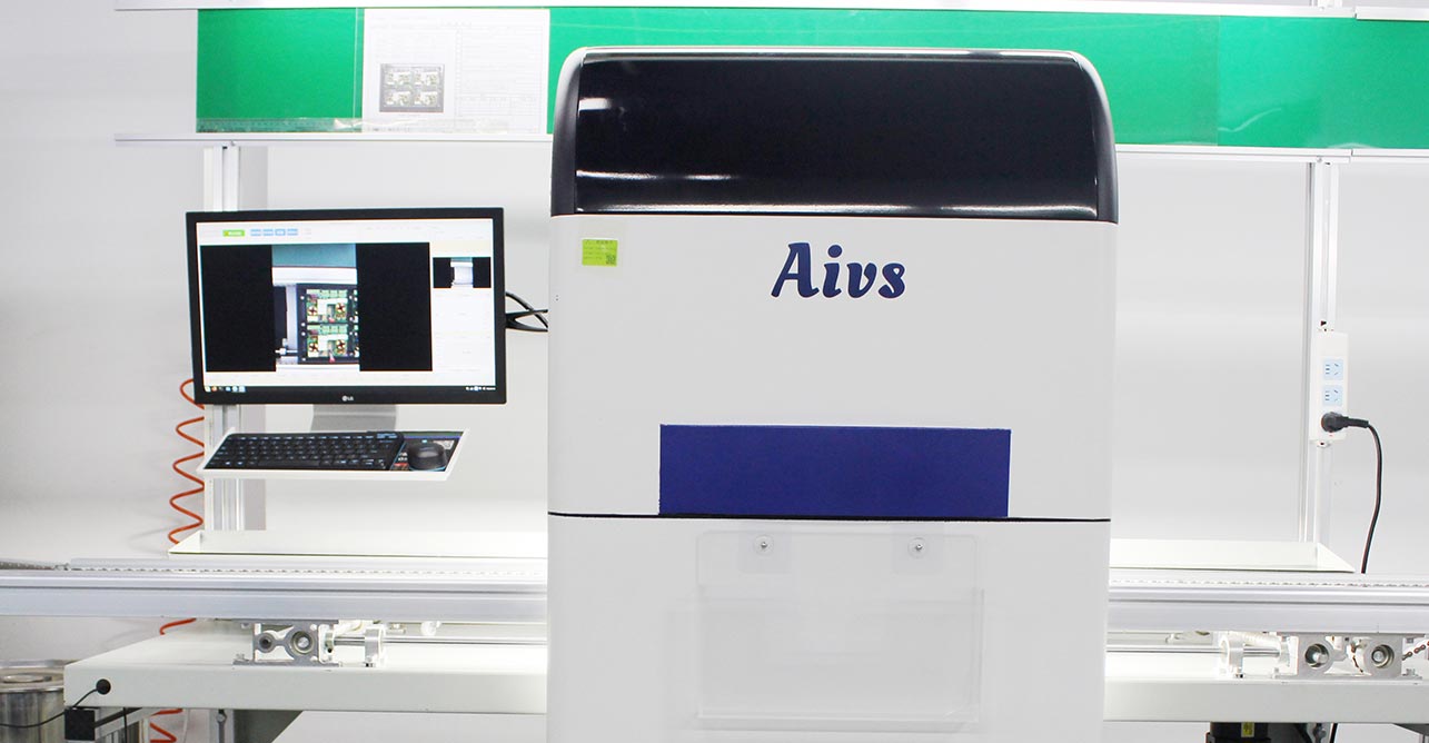
Auto Optical Inspection (AOI)for SMT
Defect detection: able to detect defects on circuit boards, such as soldering problems, missing components, short circuits, open circuits, etc., in order to ensure the quality and reliability of circuit boards.
Component Position Detection: able to detect the position and orientation of components on the circuit board to ensure the correct installation and positioning of components.
Welding quality detection: able to detect the welding quality, such as poor welding, welding short circuit, etc., to ensure the reliability and stability of the welding connection.
Printing quality inspection: able to detect the printing quality on the printed circuit board, such as printing position, printing offset, etc., to ensure the accuracy and integrity of printing.
Data analysis and recording: able to record and store the results and statistics of each inspection for subsequent analysis and traceability.
for-SMT.jpg)
First Article Inspection (FAI)
First piece verification: verify that the first piece of a new product or a new process meets the design requirements and specifications to ensure its reliability and performance.
Component Installation Inspection: Detect whether the components on the PCBA is correctly installed, welding, and welding quality to meet the requirements.
Welding quality test: detect the welding quality of the welding point, such as welding slag, bad welding, etc.
Electrical test: conduct electrical test on PCBA to verify whether the circuit connection is normal and whether the electrical performance meets the requirements.
Functional testing: Functional testing of PCBA to verify whether its function is normal.
Data analysis and recording: Record and store the results and statistics of first piece inspection for subsequent analysis and traceability.

In-Circuit Test (ICT)
Prepare test fixtures: According to the design and layout of PCBA, make corresponding test fixtures for fixing and contacting PCBA.
Connecting test instruments: Connect the test fixture to ICT test equipment, including test probes, test instruments and power supply.
Test Point Definition: According to the design and layout of PCBA, define the circuit connection points to be tested, including voltage, current, signal, etc.
Conducting tests: Place the PCBA on the test fixture, contact the test points through the test probes, and conduct electrical tests, including resistance, capacitance, inductance, short circuit, open circuit, etc.
Analyse test results: According to the feedback and test data from the test instrument, analyse whether the electrical performance of the PCBA meets the requirements.

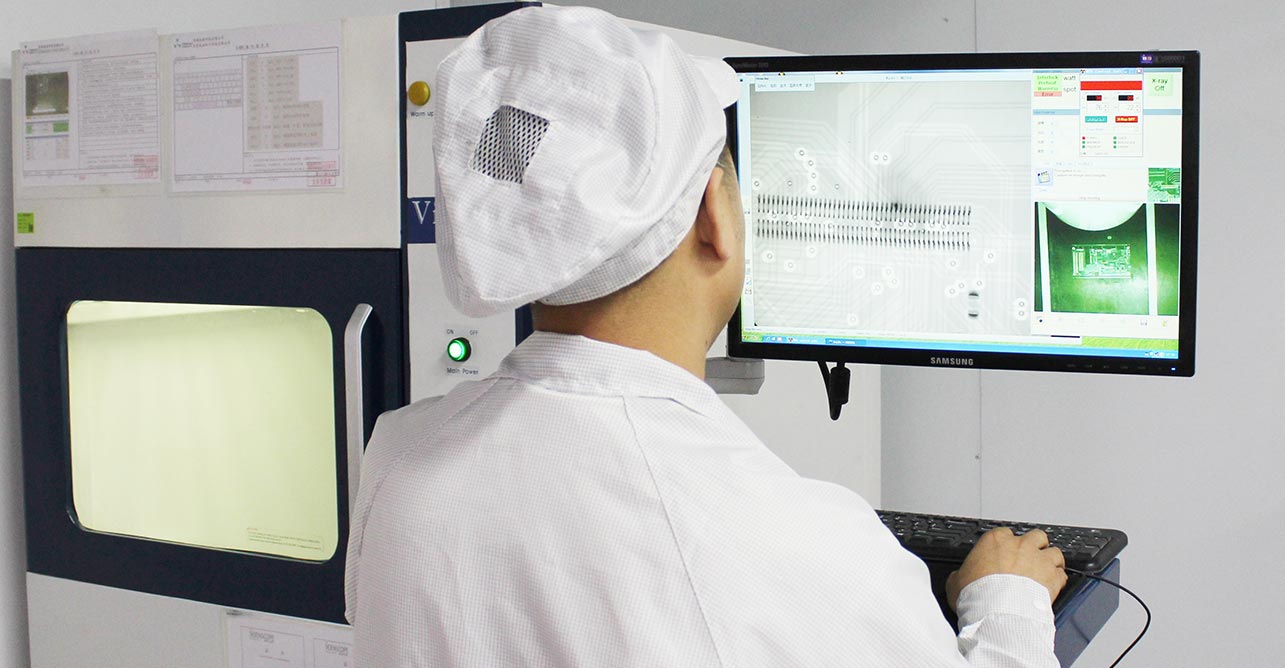
X-Ray Testing
Soldering quality inspection: Through X-ray images, it is possible to check whether solder joints are intact, whether pads are correctly connected to components, and whether there are any problems with soldering such as bubbles, cracks, or cold soldering.
Component position detection: Through X-ray image, we can check whether the components are correctly mounted on the PCBA, whether the position is accurate, and whether there is any problem of misalignment or offset.
Connected wire detection: Through X-ray images, we can check whether the wires on the PCBA are correctly connected, and whether there are problems such as short circuit, broken circuit or misalignment.
Hidden Defects Inspection: Through X-ray images, hidden defects inside the PCBA can be inspected, such as air bubbles, foreign objects, metal debris under the soldering points, and so on.
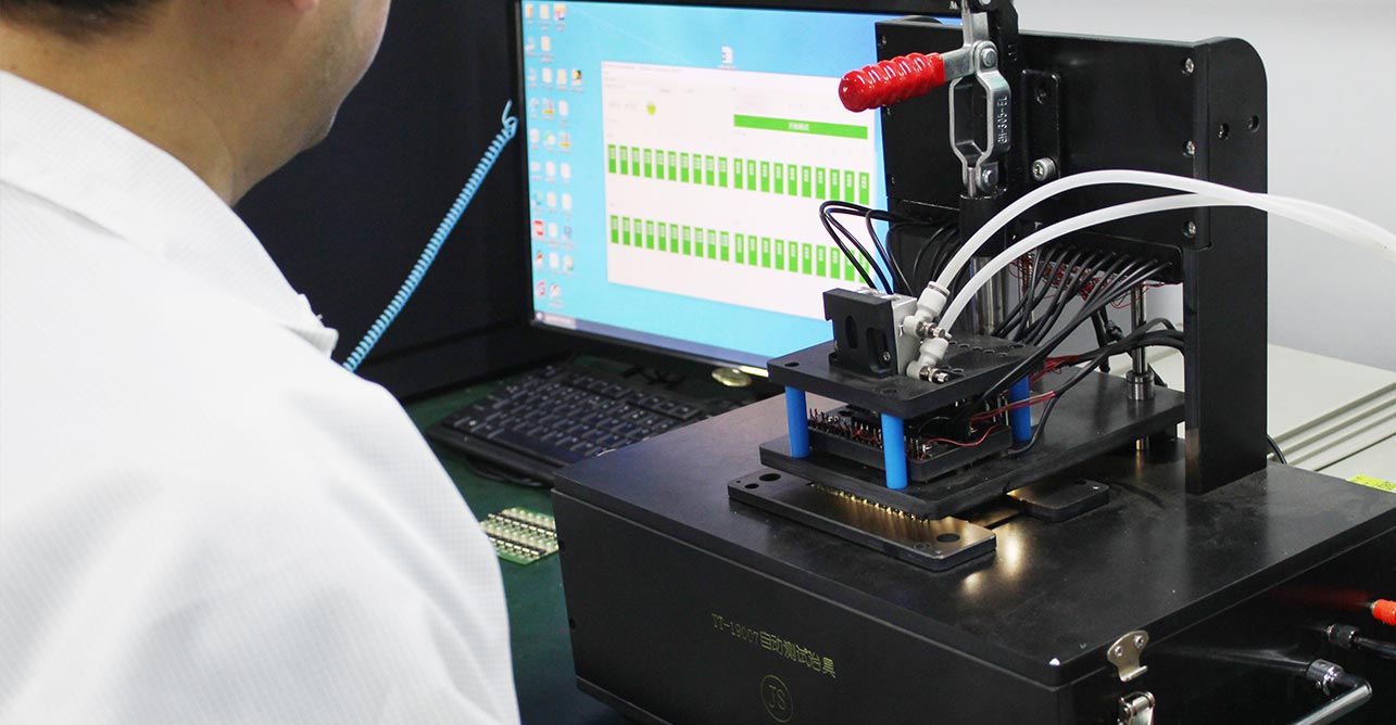
PCBA Function Testing(FCT)
Electrical testing: By testing the electrical connections, voltages, currents and other parameters on the board to ensure that the electrical performance of the board meets the design requirements. This can be done through the use of test fixtures and test instruments (e.g. multimeters, oscilloscopes, etc.).
Functional testing: Testing the operation of individual components and functions on a circuit board by simulating or using actual input signals. For example, for a control circuit board, various commands and signals can be input to test the response and output of the control circuit as expected.
Communication Test: For circuit boards with communication functions, it is necessary to test whether the communication between them and other equipment or systems is normal. This can include testing the data transmission of serial communication interfaces (e.g., UART, SPI, I2C, etc.), as well as network communication interfaces (e.g., Ethernet, wireless communication, etc.) connection and data transmission.
Temperature testing: Some boards may need to work in high or low temperature environments, so temperature testing is required to verify the board’s performance and reliability under different temperature conditions.
Reliability testing: Evaluate the reliability and durability of a circuit board by simulating its operation over a long period of time or in a specific environment. This can include vibration testing, shock testing, temperature cycling testing, etc.
AOI for DIP
The DIP insert AOI inspection system usually consists of a conveyor system, a camera, and a light source. the DIP insert on the PCB is moved through the conveyor system into the field of view of the camera, which captures a high-resolution image of the DIP insert. These images are processed and analysed, and using advanced image processing algorithms and template matching technology, defects in the DIP inserts can be detected, such as missing, misaligned, incorrect polarity, bent or damaged pins, soldering issues, etc.
The DIP plug-in AOI inspection system can compare with CAD data or predefined reference images to identify any defects or anomalies. When defects are detected, the system can trigger alarms, flag faulty inserts, or even automatically reject the entire PCB.
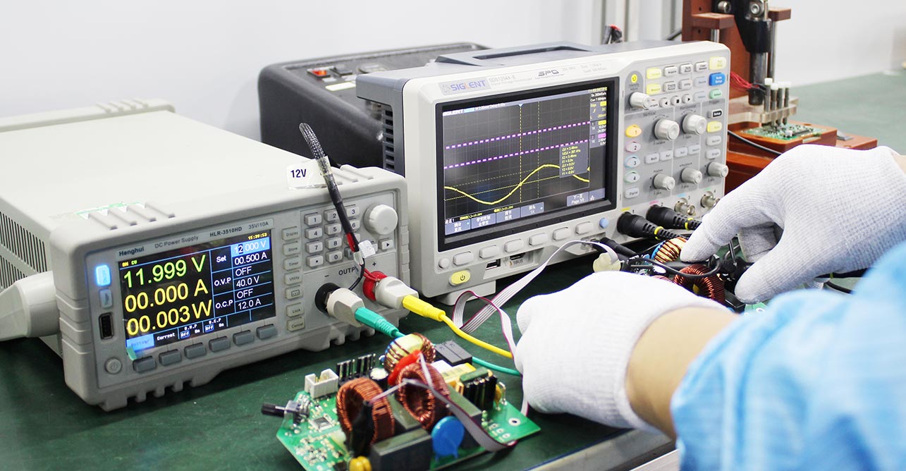
PCBA Electric Performance Testing
Preparation of test equipment: First of all, it is necessary to prepare test equipment applicable to PCBA, such as multimeters, oscilloscopes, signal generators and so on. These devices will be used to measure and verify the electrical parameters and performance on the PCBA.
Connect the test equipment: Connect the test equipment to the test interface on the PCBA. This can be done by connecting wires or test fixtures, etc. Make sure the connection is correct and stable.
Measure Electrical Parameters: Use the test equipment to measure various electrical parameters on the PCBA, such as voltage, current, frequency, resistance, etc. This can be done either by direct measurement or by applying a specific test fixture. This can be done by direct measurement or by applying specific test signals.
Verify Functionality: Verify that the various functional modules of the PCBA are working properly by applying appropriate test signals and analogue inputs. This can include input and output ports, communication interfaces, sensors, actuators, etc.
Perform Load Testing: Under normal operating conditions, apply appropriate loads to the PCBA to verify its performance and stability under load. This can include testing the stability of the power supply, the impact of temperature changes on circuit performance, etc.
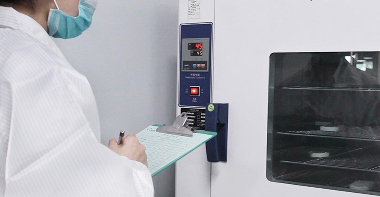
PCBA Aging Test
Designing the aging test programme: According to the design specifications of the PCBA and the environment in which it is to be used, the parameters and conditions of the aging test are determined. This includes aging time, temperature, humidity, voltage and so on. You can refer to relevant industry standards or empirical data for design.
Set up aging test equipment: Prepare equipment suitable for aging test, such as aging box, constant temperature and humidity box, power supply regulator and so on. According to the test programme to set the parameters of the equipment, such as temperature, humidity, voltage and so on.
Place the PCBA in the aging test equipment: Place the PCBA in the aging test equipment and make sure its connection with the test equipment is stable. According to the conditions set in the test programme, expose the PCBA to the corresponding environment.
Run the aging test: according to the time set in the test programme, run the aging test. During the period, monitor the PCBA’s electrical parameters and performance changes, such as voltage, current, frequency, resistance, etc.. Test equipment can be used for real-time monitoring or regular sampling.
Verify aging test results: After the aging test is completed, conduct functional and performance tests on the PCBA to verify its reliability and stability under aging conditions. This can include verifying functional modules, communication interfaces, input and output ports, etc.
Record and Report: Record the results of the aging test and generate the corresponding test report. This helps with quality control and traceability, as well as subsequent product maintenance and improvement.
Quality Management System
Quality Management System (QMS) refers to the management system that directs and controls the organization in terms of quality. The quality management system is a systematic quality management mode established within the organization and necessary to achieve quality objectives. This is a strategic decision of the organization. It helps organizations to maintain quality standards and improve their performance over time.
Quality management systems help businesses identify potential problems before they occur, allowing them to take corrective action quickly and efficiently. They also help businesses stay organized by providing a systematic approach to quality assurance, ensuring that all processes are followed correctly and consistently. Quality management systems can also be used to measure performance, helping businesses identify areas for improvement and make necessary changes in order to keep up with changing customer needs.

Quality System and Industrial Standard
We meet the following requirements in the quality system:
ISO9001 quality management system
ISO14001 Environmental Management system
ISO13485 medical device quality management system
UL, SGS, RoHS
Comply with IPC-610
All components comply with IPC-A-610H– Classes I to III
Choosing Our Services Reduces The Quality Risk And Provides a Solid Guarantee For The Successful Market Entry of Your Products.